Problem Statement
I have been trying out different structural FE software to evaluate their automatic reinforcement design functions. For an underground structure, multi-layer reinforcement design in SLS is a must. Surprisingly, most of the STR FE tools cannot handle multi-layer reinforcement very well. Typical problems are:
- Software does not have the capability to add the second or third layer at deeper positions automatically - instead it usually places them at the same depth as the first layer.
- FEM-Design does a great job at SLS design - but unfortunately, all additional reinforcement is placed on the first layer.
- Software can check multi-layer reinforcement, but it can only check one arrangement - it cannot do an automatic design.
- Software can do multi-layer design, but only for ULS, it can check SLS for the reinforcement defined by ULS.
- I can guess that this is pretty useful for above-ground structures, but for underground structures, SLS usually governs our reinforcement design.
Best Practice at the Moment
There are a LOT of STR FE tools and I am not claiming that I am aware of the capabilities of all of the ones out there. (Please reach out if you know more - so I can try them out or I can update the post with new information.) But at least, I have tried SOFiSTiK, FEM-Design, Robot, Lusas, RFEM6. I know that SOFiSTiK can do multi-layer design, but not without simplifications. User is asked to define the multi-layer reinforcement arrangement by LAY method. This requires a fixed diameter and minimum-maximum area of reinforcement for each layer.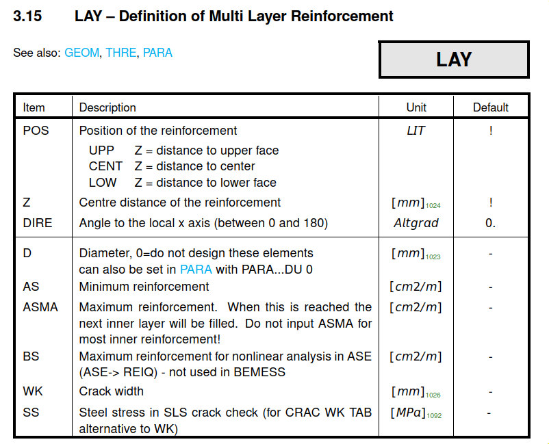
Using these inputs, SOFiSTiK can produce continuous As maps, required reinforcement area, for SLS. That’s great! But how does it achieve this really? In short:
The crack width design is done for the most outer layers, but the inner layers participate on the
reinforcement ratio and the effective height
It uses an averaging method to achieve a single layer reinforcement system. I tried to explain this in the sketch below. Basically, the area, depth and diameter of inner layers are scaled down in the ratio of the steel stress at that level to the steel stress at the outermost layer. This helps the tool to reduce the multi-layer system to a single layer problem.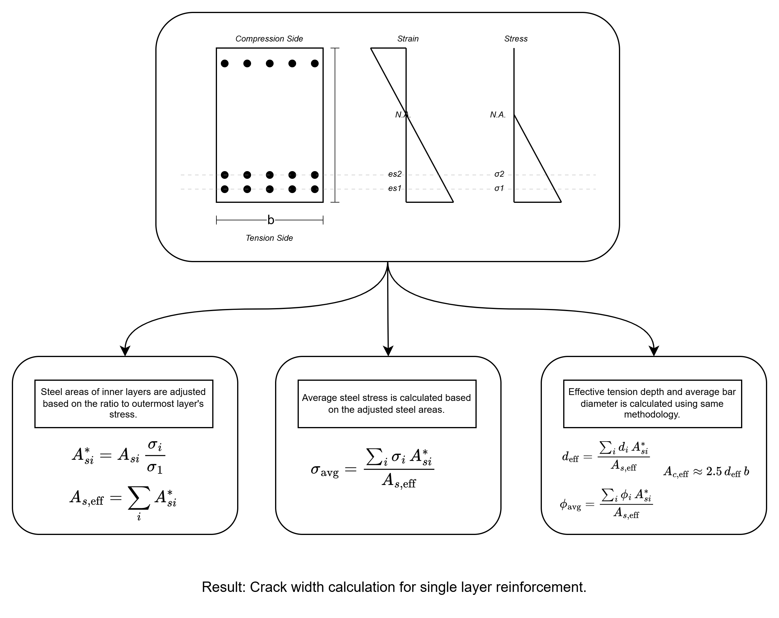
We have a problem: Crack width depends on the diameter
Crack width depends on the diameter. As we have seen above, SOFiSTiK provides auto reinforcement design by fixing the diameter per layer.
That’s OK - but then, we should write it in bold:
Required reinforcement area map
You can use this colourful map only for the chosen reinforcement diameter!
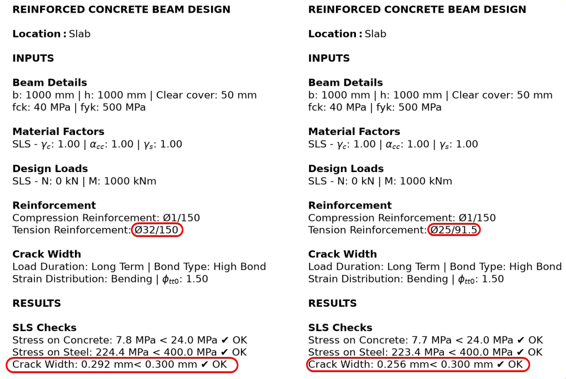
You cannot just take a map that’s been prepared for Ø25 diameter and design a K32/150 reinforcement. It doesn’t work that way. As you can see in the comparison below, keeping the area essentially the same (K25/91.5 = K32/150 = 53.6 cm²/m) but changing the diameter from Ø25 to Ø32 raises the crack width from 0.256 mm to 0.292 mm, i.e. the utilisation against the 0.30 mm limit rises from about 85% to 97%.
Colourful and Continuous Maps
Why do we need continuous maps always? Why can’t we have discrete maps? Is the actual reinforcement layout continuous? Of course not.
The problem is that those maps do not mean much to an engineer. The engineer still checks for typical reinforcement areas on those maps. They look for 53.6 cm2/m so that they can see where they should put K32/150. We even adjust the colour map ranges to fit the typical reinforcement areas.
In summary, I don’t believe continuous maps are in any way better than discrete reinforcement maps. Why do I focus on this? We’ll come to that.
Remark for SCIA
Without going into the details of the software and just reading their pages, I suspect SCIA might be doing something relevant here. But my guess is that, right now, it is mainly limited to 1D members. Because, the texts below are mostly from 1D member pages and my experiments with the trial version resulted in one layer reinforcement.
In this page
, they say:
In case the required area of reinforcement exceeds the available space on one layer, more layers (with adapted lever arm) are automatically generated. Designed reinforcement is automatically recalculated to real bars afterwards.
And here , at least for 1D members, we can see the multi-layer design announcement.
Required reinforcement for ULS is simpler
Please be aware - we are discussing the required reinforcement calculation for SLS, not ULS. The ULS side of the discussion is simple, and the reason is fundamental: ULS capacity is governed by the steel force, an area times a fixed design stress. The bar diameter enters only through a tiny lever-arm correction (d = h − c − φ/2), so the required area inverts cleanly in one step. Crack width, by contrast, depends on the diameter explicitly through srmax, so “required area” is undefined until a diameter is chosen. To name a few, RFEM6, FEM-Design and LUSAS can provide the required reinforcement for ULS easily.
For example, LUSAS says:
The RC Slab design facility enables calculation of required steel reinforcement areas for ULS loadcases and calculation of crack widths for SLS loadcases.
RFEM6 RF-Concrete Surfaces Manual says:
In the serviceability limit state, no required reinforcement is determined; instead, the provided
reinforcement is used to determine the actually provided strain ratio.
How to solve the problem?
Coming back to our initial problem: We want to have a tool to design multi-layer reinforcement for SLS cases. A simple request, if you ask me.
I am sure this post will be outdated before long - if I am not already missing methods to overcome this problem. It might have already been solved in other FE tools that I don’t have access to right now.
But to solve the issue at the hand, I have worked on a automatic reinforcement designer tool for a couple of nights. For many years, I have had my own reinforcement calculation code in Python (you can see in the comparison above) which is basically a Python version of the reinforcement design spreadsheet I’ve been using over the years. Using that as a basis, I created a FE shell reinforcement tool. No workaround or simplification.
How does it work?
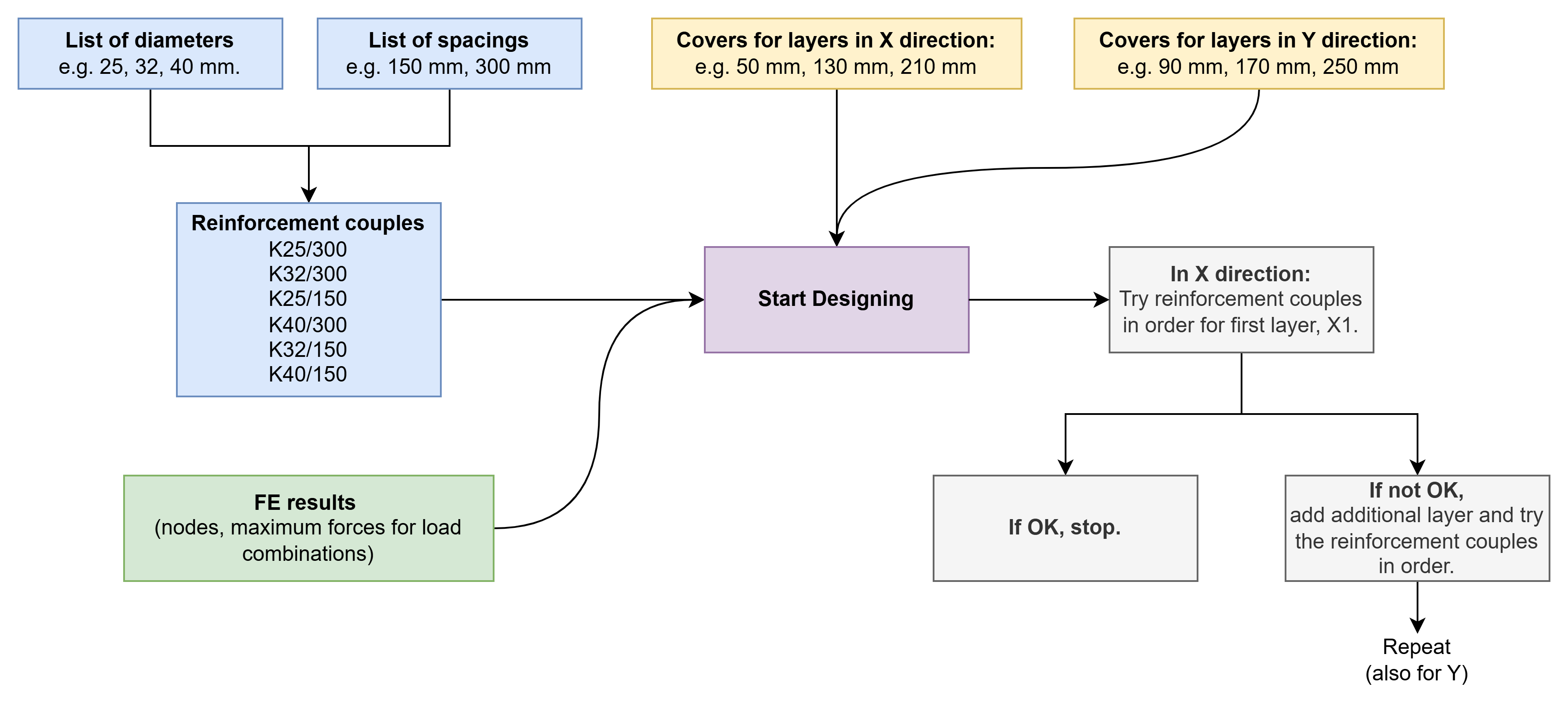
We provide the list of reinforcement diameters and spacings that we want to use in our design. Based on these diameters and spacings, the code prepares reinforcement couples to try at each node.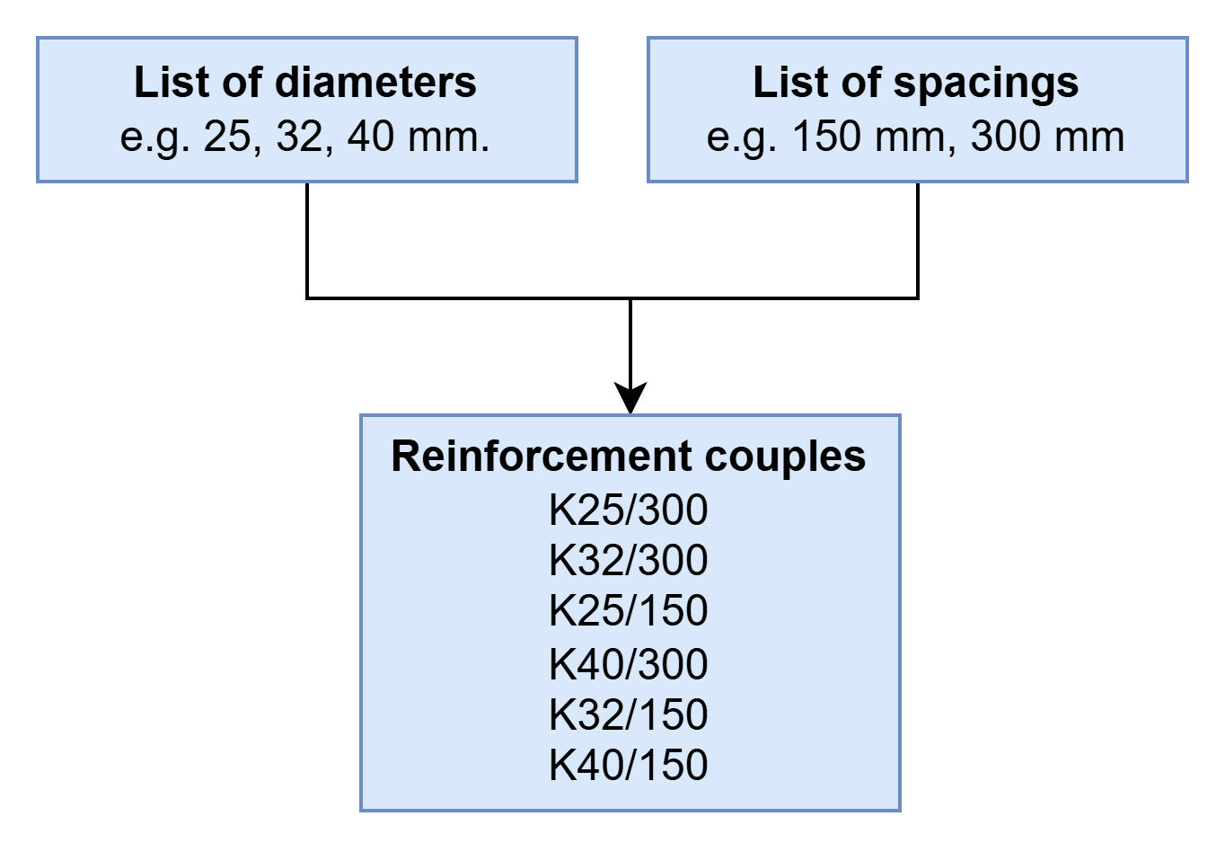
For both directions, we provide the cover depth for each reinforcement layer, whether or not it ends up being used.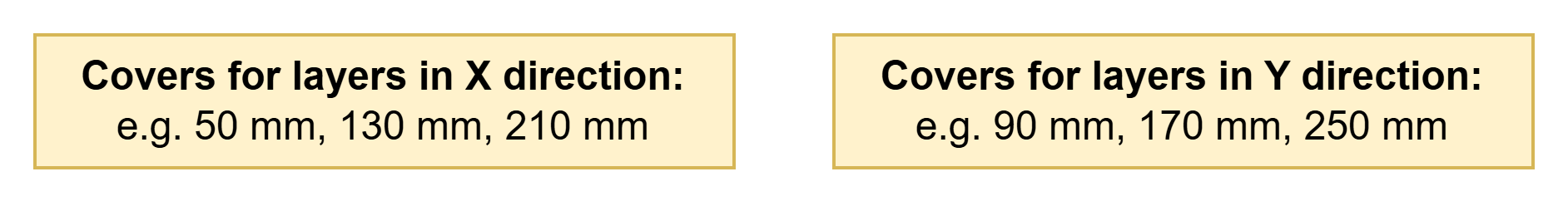
We also provide the FE results in a spreadsheet which includes nodes and maximum forces for load combinations (providing the pre-reduced maximums keeps the runtime down, but it can also solve for all load combinations).
That’s it.
Then the code starts to work. For each node, it takes the force and iterates through reinforcement couples for the given layer depth (and other inputs such as fck, creep factor etc. - all the others required for SLS and ULS calculations.) If it finds a reinforcement couple that satisfies the requirements, it stops. If not, it tries until the maximum reinforcement, and then moves on to the second layer. When the first layer reaches its largest couple without satisfying the checks, it is held fixed at that maximum, and the search begins adding bars to the second layer.
Overall process is shown below.
In action
As described above, reinforcement inputs (diameter, spacing and cover depths) are provided by the user.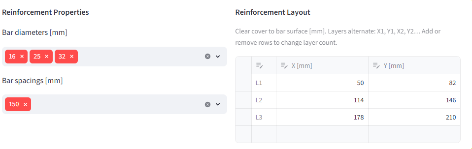
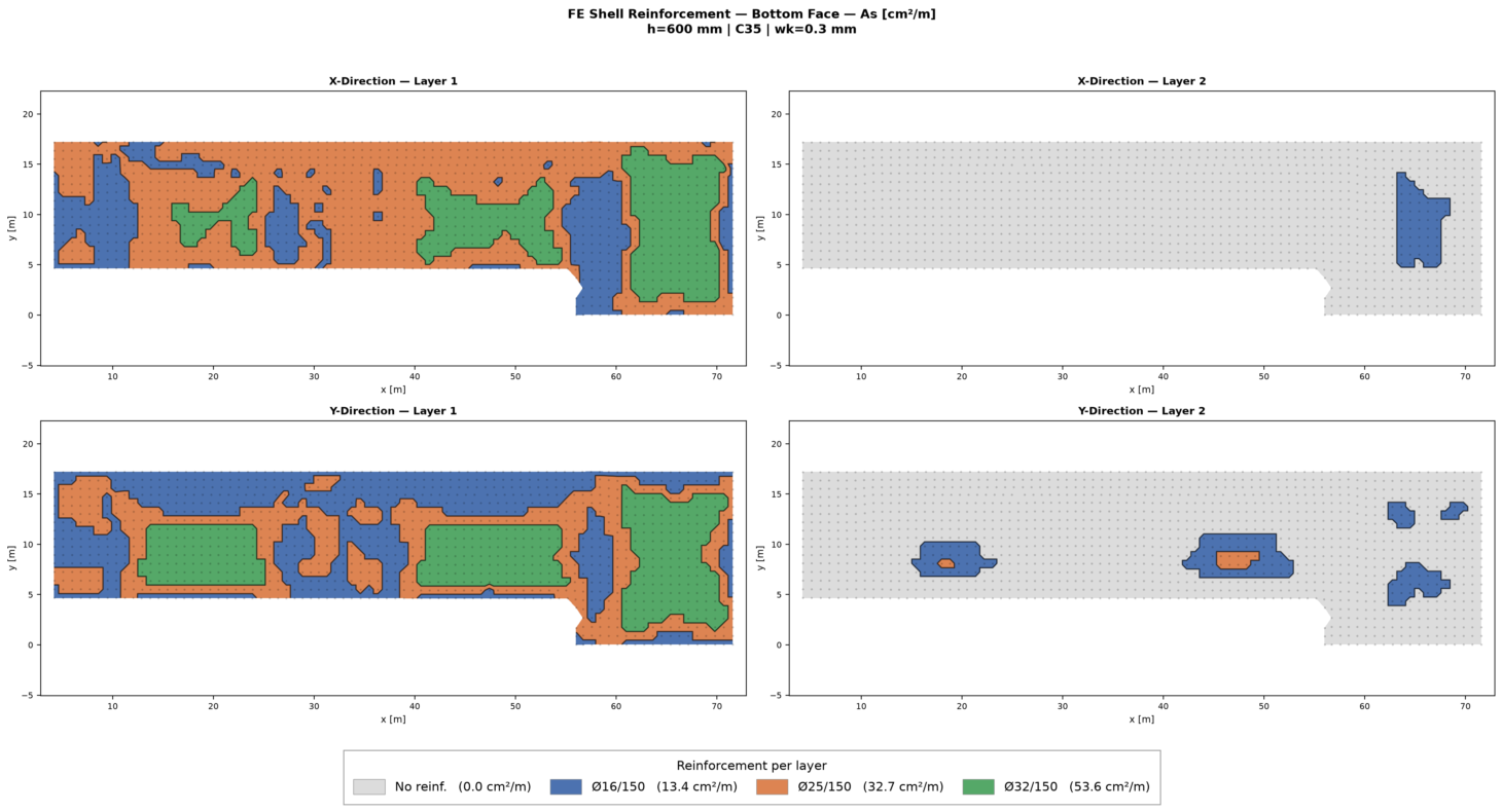
Then, for each node, reinforcement requirements are calculated. Now, the user can see clearly where they need which reinforcement.
And this time, the reinforcement shown in the figure is exactly correct - because we are not working with As, the area of the reinforcement. We are working directly with the reinforcement couples.
Of course, if the user chooses a single reinforcement diameter and varying bar spacings, the results will be the same as SOFiSTiK. However, in real life we usually fix the spacing - not the diameter.
Why I wouldn’t use my tool
Wood-Armer vs. Baumann
Because, I use Wood-Armer method - which takes into account the torsion moments. This is working very well for cases when we have uni-axial bending (i.e. Mx is dominant, My is low), however, when we have bi-axial bending (Mx ≈ My > 0), the principal stress direction (i.e. cracking direction) is not aligned with the reinforcement direction. That means our reinforcement is not working as well as it could.
Wood-Armer based methods cannot check this. A simple example you can try is a square plate that is fully fixed on all edges with distributed load on top. This slab has a Mx=My>0 and Mxy=0 at the middle. That means, Wood–Armer just hands back Mx and My unchanged, it adds nothing for the diagonal crack. However, if you try Baumann method (which is implemented in most Germany-based packages such as RFEM6 or SOFiSTiK), it will tell you that the principal direction of the cracking is 45 degree to the X and Y. That’s why it will need more reinforcement than what you calculate by hand or spreadsheet - and in this case, the tool I presented above.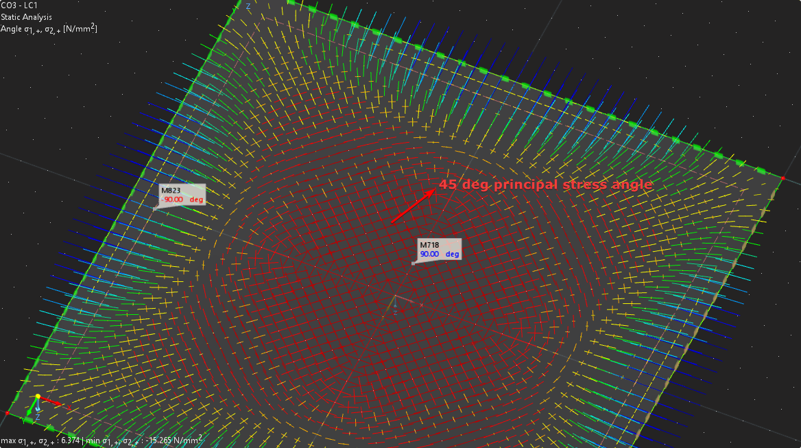
Replicating Baumann’s resulting-direction crack check outside a proper FE package is quite hard, and I can’t devote the time to it. So for biaxial bending where the crack direction matters, I rely on the developers of these excellent FE packages to update the tools in the near future.
Calculation Cost
I am quite certain this is the most computationally expensive way to do the SLS multi-layer reinforcement calculation. And there are many ways to improve this scheme. However, calculation time is not the only concern we have. We should be able to derive automatically generated reinforcement maps that can be verified by our spreadsheets. Our old spreadsheets should not be “better” than our state-of-the-art FE packages.
Conclusion
As I said: this post can be outdated at any moment. These tools are developed at a very fast pace, and there are many I haven’t tried (or maybe even heard of). So, if you reach out with information about other software, I will be glad to edit the post to add it.
Otherwise, this is what we need, and I am sure we will get there soon. So, until then, take this as an open letter to the tired developers of these amazing packages.